Team Tasks
Lab Description
In this lab, we used the various functionalities of the Arduino Uno and the Arduino IDE, as well as the GitHub repository to come up with a basic Microcontroller. The purpose of our Microcontroller is to serve as the logical control unit of our final Robot.
As described in various parts of this lab report, we brainstormed and constructed a simple functional Arduino program, using multiple external components and the Arduino Uno in this lab session.
We then put together our robot and had it perform a simple autonomous task.
To demo the robot's movement, we set values to the servos to make the robot go forward, waited as it did so, then set values for it to turn, waited for it to turn, and repeated. Since the code in the loop repeats naturally, this was easily implemented.
Lab Materials
* 1 Arduino Uno (in the box)
* 1 USB A/B cable (in the box)
* 1 Continuous rotation servos
* 1 Pushbutton
* 1 LED (any color except IR!)
* 1 Potentiometer
* Several resistors (kΩ range)
* 1 Solderless breadboard
Part 1 - Communicating between the Uno and IDE
Our first task was to get the internal LED on the Arduino Uno to blink. In the Arduino IDE, we navigated to File > Examples > 1.Basics > Blink. This opened up the "Blink" example sketch. To program the Arduino, we first compiled the code by clicking the checkmark and then uploaded it by clicking on the right-pointing arrow. Once the code uploaded, the internal LED blinked on and off every second.
Blink sketch uploaded to the Arduino:
  /*
    Blink

    Turns an LED on for one second, then off for one second, repeatedly.

    Most Arduinos have an on-board LED you can control. On the UNO, MEGA and ZERO
    it is attached to digital pin 13, on MKR1000 on pin 6. LED_BUILTIN is set to
    the correct LED pin independent of which board is used.
    If you want to know what pin the on-board LED is connected to on your Arduino
    model, check the Technical Specs of your board at:
    https://www.arduino.cc/en/Main/Products

    modified 8 May 2014
    by Scott Fitzgerald
    modified 2 Sep 2016
    by Arturo Guadalupi
    modified 8 Sep 2016
    by Colby Newman

    This example code is in the public domain.

    http://www.arduino.cc/en/Tutorial/Blink
  */

  // the setup function runs once when you press reset or power the board
  void setup() {
    // initialize digital pin LED_BUILTIN as an output.
    pinMode(LED_BUILTIN, OUTPUT);
  }

  // the loop function runs over and over again forever
  void loop() {
    digitalWrite(LED_BUILTIN, HIGH);   // turn the LED on (HIGH is the voltage level)
    delay(1000);                       // wait for a second
    digitalWrite(LED_BUILTIN, LOW);    // turn the LED off by making the voltage LOW
    delay(1000);                       // wait for a second
  }
Video of internal LED blinking once the Blink sketch was uploaded:
Part 2 - Modifying the Blink sketch
Next, we needed to modify the Blink sketch to now make an external LED blink on and off every second. First let's start with connecting the LED to the Arduino. We placed our LED onto the breadboard, connecting the anode of the LED (the longer leg) to digital pin 12 on the Arduino with a wire, and the cathode (the shorter leg) to the GND (ground) pin on the Arduino with a wire. To prevent shorting out any pin on the board or any components themselves, we placed a 1.5 kΩ resistor in series with the LED before connecting it to digital pin 12. The only modification that needed to be made in the Blink sketch was changing LED_BUILTIN to 12, to denote digital pin 12 where the external LED was connected. This change was made both within void setup() and void loop().
Modified Blink sketch which blinks an external LED on and off every second:
  // the setup function runs once when you press reset or power the board
  void setup() {
    // initialize digital pin 12, to which the external LED is connected, as an output.
    pinMode(12, OUTPUT);
  }

  // the loop function runs over and over again forever
  void loop() {
    digitalWrite(12, HIGH); // turn the LED on (HIGH is the voltage level)
    delay(1000);            // wait for a second
    digitalWrite(12, LOW);  // turn the LED off by making the voltage LOW
    delay(1000);            // wait for a second
  }
Video of external LED blinking once the modified Blink sketch was uploaded:
Part 3 - The Serial Monitor and the Analog Pins
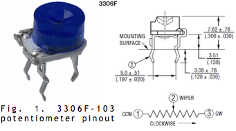
In this part of the lab, we utilized the Uno's analog pins. An analog pin only works as an INPUT, which removes the need to configure it as an INPUT within void setup(). We used a potentiometer to input a range of different analog voltages and then printed the values to the screen using the Serial Monitor. The potentiometer we used has three pins and a diagram can be seen below. The potentiometer was placed on the breadboard and its center pin was connected in series with a 1.5 kΩ resistor to analog pin A5 with a wire. Out of the remaining two pins, one was connected to GND on the Arduino and the remaining pin was connected to +5V. Since we used the Serial Monitor to print out voltage values, in void setup() we needed to set the rate at which data will be read in. We picked 9600 bps (bits per second) as it is a commonly used value. Again, analog pin A5 did not need to be set up as an input. Within void loop(), the analog voltage value of the potentiometer is read and then printed to the Serial Monitor. As the potentiometer knob is turned CCW (counter-clockwise) the input voltage decreases in value, whereas turning it CW (clockwise) increases the voltage.
Diagram of potentiometer connected to the Arduino Uno:
Code for inputting variable analog voltages using potentiometer:
      // create variable to refer to analog pin connection of the potentiometer
     int pot = A5;

     void setup() {
        // set data rate to 9600 bps (bits per second)
       Serial.begin(9600);
     }

     void loop() {
       // read the input analog voltage
       int analogValue = analogRead(pot);
       // print voltage value (on a new line) to Serial Monitor
       Serial.println(analogValue);
     }
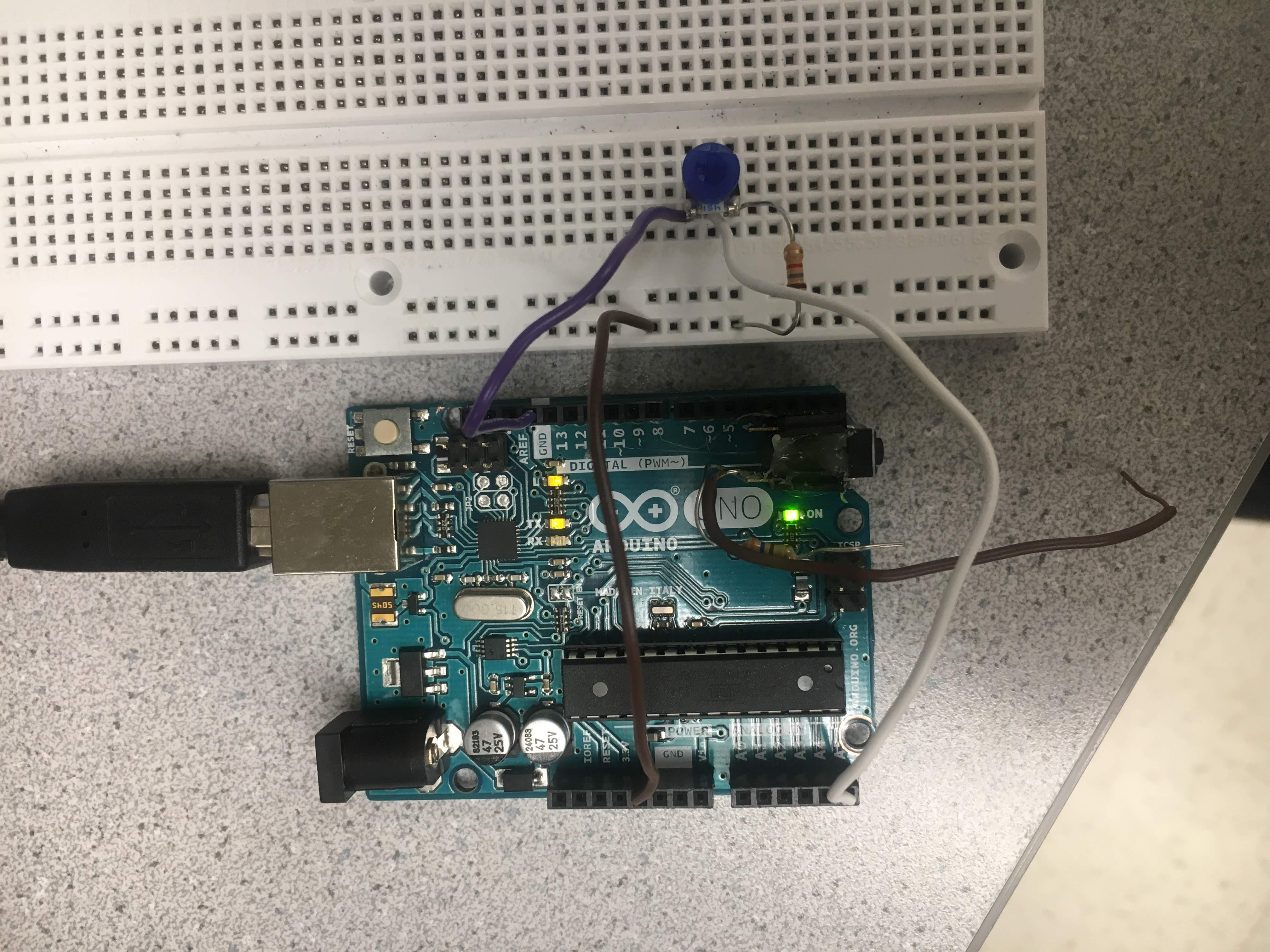
Photo of the potentiometer circuit:
Next, we added an LED to our circuit and used the potentiometer to control the brightness of the LED. We connected the LED up to a digital pin with PWM capability. PWM is pulse width modulation: the Arduino can actually only output digital values, but PWM can create an analog output using digital means. PWM outputs a fast square wave, with differing on and off times. Because the square wave is so fast, it averages out, effectively creating an analog value. We can write an analog value between 0 and 255 to a PWM value. A higher PWM value is a higher duty cycle, analogWrite(255) is 100% duty cycle, meaning the pin that is being written will always be high.
Code for adding LED to existing circuit:
        // create variable to refer to analog pin connection of the potentiometer
       int pot = A5;
       // create variable to refer to LED pin connection
       int led = 11;

       void setup() {
          // set data rate to 9600 bps (bits per second)
         Serial.begin(9600);
         pinMode(led, OUTPUT);
       }

       void loop() {
         // read the input analog voltage (will be a value between 0 and 1023)
         int analogValue = analogRead(pot);
         //map this value to a value between 0 and 255
         analogValue = map(analogValue, 0, 1023, 0, 255);
         analogWrite(led, analogValue);
       }
Video of potentiometer-controlled LED output:
Part 4 - Using the Parallax servos
Since our robot is to move using Parallax Continuous Rotation Servos, in this section of the lab we first began by connecting one servo to the Arduino. The white cable was connected to the PWM pin 5 (pulse-width-modulated), the VCC (5V) red cable was hooked up to the voltage output pin on the Arduino board, and the black wire was connected to the GND pin.
Code for utilizing servo:
  #include
  Servo servo;

  void setup() {
    servo.attach(5);
  }

  void loop() {
    servo.write(180);
    delay(1000);
    servo.write(90);
    delay(1000);
    servo.write(0);
  }
After we experimented with getting the servo to rotate in either direction and to stop, we connected the potentiometer to the Arduino to be able to control the servo's speed. In our potentiometer code below, we labeled the servo and mapped it between values 0 and 180 to sync its movement to that of the potentiometer.
Code for controlling servo with potentiometer:
  #include
  // create variable to refer to analog pin connection of the potentiometer
  int pot = A5;
  Servo servo;

  void setup() {
    servo.attach(5);
  }

  void loop() {
    int analogValue = analogRead(pot);
    //map this value to a value between 0 and 180
    analogValue = map(analogValue, 0, 1023, 0, 180);
    servo.write(analogValue);
  }
Video of potentiometer-controlled Servo control
Part 5 - Assembling the robot!
We constructed the Robot as follows:
Each servo motor had a matching wheel attached. Since we found wheels that fit the motors directly, we did not utilize the spokes or screws when attaching the wheels. The motors driving the wheels were attached to the underside of the large white piece, henceforth referred to as the main chassis, via plastic struts. A red peg was attached to the front of the main chassis, in which we placed a ball bearing. This was intended to create a level platform for the components atop the main chassis while still allowing the robot to move and turn freely with the two servo-powered wheels. While it served the former function quite well, the peg we obtained was slightly too short for the ball bearing to engage, so it more slid than rolled on this component. Atop the main chassis we attached the breadboard with Velcro. We anchored the Arduino to the breadboard directly by lashing it with a rubber band. We used a similar method to attach the battery to the main chassis. This construction was meant to be temporary, and would be refined in later labs.
Robot demo
With our robot constructed and the servos hooked up to the Arduino, we were now able to make it move. For simple forward locomotion, we assigned each servo a value equidistant from 90 in opposite directions (i.e. 180 and 0). To visualize why, consider viewing the robot from the right side. Looking at the wheel on that side, a clockwise rotation would propel the robot forward. However, looking at the robot from the left, anti-clockwise motion would result in forward propulsion. As such, we needed to make the servos spin in 'opposite' directions to make both wheels spin 'forward.' For a similar reason, assigning the same value to both wheels caused to robot to turn. Depending on which side of 90 the value fell, it would turn either right or left.
To demo the robot's movement, we set values to the servos to make the robot go forward, waited as it did so, then set values for it to turn, waited for it to turn, and repeated. Since the code in the loop repeats naturally, this was easily implemented.
    #include
    Servo left;
    Servo right;

    void setup() {
      left.attach(5);
      right.attach(10);
    }

    void loop() {
      //STRAIGHT
      left.write(180);
      right.write(0);
      delay(1000);

      //TURN
      left.write(45);
      right.write(45);
      delay(1000);
    }
Quick Blooper
As with all projects, not everything goes perfectly at first! We made sure to fix by using firmly fitted wheels as seen in the video below.