Team Tasks
Lab Description
In this lab, we integrated the work from previous labs and milestones. We integrated the microphone circuit into the robot so that the robot could start on a 660 Hz tone. We then had out robot navigate a maze on its own, and send the maze information wirelessly to a base station. The base station displayed the updates on a screen.
Radio Communication
The structure we devised to store the information about the maze was as follows:
- store maze info in 81 long (9x9) byte array of Square data struct
- each square contains 8 bits of information packed into a struct
- 4 bits (1 for each wall)
- change from left-right-fwd to N-E-S-W
- 1 bit for detecting robot
- 3 bits for treasure
- 1 bit for color, 2 for shape
- shape(0,0) == no treasure
- update fields accordingly, transmit data in packets
- if at position 4,5 update 4,5 entry in array
- not sure if we should send raw maze info or decoded
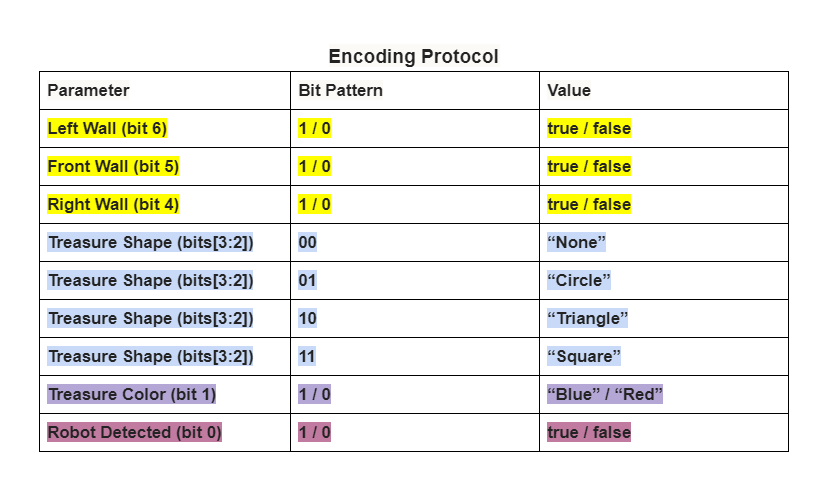
We decided to send a 7-bit package of each square iteration. The three most significant bits represents the left, front, and right walls. The least significant bit represents a robot’s IR hat being detected. The remaining three bits are for treasures, two for its shape and one for the color. A shape of 00 corresponds to no treasure, in which case the color was ignored.
        //print the position
        Serial.print(posY);
        Serial.print(",");
        Serial.print(posX);
        Serial.print(",");

        //decodes walls and prints all valid wall info
        robot_detected = bitRead(got_response, 0);
        left_wall = bitRead(got_response, 6);
          front_wall = bitRead(got_response, 5);
          right_wall = bitRead(got_response, 4);
          back_wall = 0;
          switch (orient) {
            case 0:
              if (front_wall) Serial.print("north=true,");
              if (left_wall) Serial.print("west=true,");
              if (right_wall) Serial.print("east=true,");
              break;
            case 1:
              if (front_wall) Serial.print("east=true,");
              if (left_wall) Serial.print("north=true,");
              if (right_wall) Serial.print("south=true,");
              break;
            case 2:
              if (front_wall) Serial.print("south=true,");
              if (left_wall) Serial.print("east=true,");
              if (right_wall) Serial.print("west=true,");
              break;
            case 3:
              if (front_wall) Serial.print("west=true,");
              if (left_wall) Serial.print("south=true,");
              if (right_wall) Serial.print("north=true,");
              break;
            default:
              break;
          }

        //generate seen as in Milestone 2
        int seen = (got_response & B1110000) >> 4;
        if (got_response & B1) seen |= B1000;

        //figure out nextOrient based on turning logic
        switch (seen) {
                  case B0010:
                    //wall in front only!! turn left
                    nextOrient--;
                    break;
                  case B1000:
              //robot in front only, turn left
                    nextOrient--;
                    break;
                  case B0110:
                    //wall in front and left, turn right
                    nextOrient++;
                    break;
                  case B0011:
                    //wall in front and right, turn left
                    nextOrient--;
                    break;
                  case B0111:
                    //wall in front, right and left, turn around
                    nextOrient+=2;
                    break;
                  case B1100:
                    //wall on left, robot in front, turn right
                    nextOrient++;
                    break;
                  case B1001:
                    //wall on right, robot in front, turn left
                    nextOrient--;
                    break;
                  case B1101:
                    //wall on right and left, robot in front, turn around
                    nextOrient+=2;
                    break;
                  //weird cases
                  case B1110:
                    //wall on left and front, robot in front?, turn right
                    nextOrient++;
                    break;
                  case B1011:
                    //wall on right and front, robot in front?, turn left
                    nextOrient--;
                    break;
                  case B1111:
                    //wall on right and left and front, robot in front?, turn around
                    nextOrient+=2;
                    break;
                  default:
                    //go straight
                    break;
            }

        //wrapping around for nextOrient
        if (nextOrient == -1) nextOrient = 3;
        if (nextOrient ==  4) nextOrient = 0;
        if (nextOrient ==  5) nextOrient = 1;

        //figure out where we're going based on nextOrient
          switch (nextOrient) {
            case 0:
              nextPosY= posY-1;
              break;
            case 1:
              nextPosX= posX+1;
              break;
            case 2:
              nextPosY= posY+1;
              break;
            case 3:
              nextPosX= posX-1;
              break;
            default:
              break;
          }

        //finally, update pos and n
        posX = nextPosX;
        posY = nextPosY;
        orient = nextOrient;

        //print treasure info
        //print if robot seen
              Serial.print("tshape=");
              int t_shape = (got_response & B1100) >> 2;
              if(t_shape == B00) Serial.print("None");
              else if(t_shape == B01) Serial.print("Circle");
              else if(t_shape == B10) Serial.print("Triangle");
              else Serial.print("Square");
              Serial.print(",tcolor=");
              int t_color = bitRead(got_response, 1);
              if(t_shape == B00) Serial.print("None");
              else if(t_color == B0) Serial.print("Red");
              else Serial.print("Blue");
              if (robot_detected) {
              Serial.println(",robot=true");
              }
              else Serial.println(",robot=false");
We set up logic to interpret the data sent over the radio once received. It translates the front, left, and right walls in to north, south, east and west walls, as well as updating the position and orientation of the robot in the maze.
We set up a sequence of fake data packets formatted as described above to be transmitted over the radio to simulate our robot going through the maze. The base station then decoded these packets and generated the serial prints to interface with the GUI.
System Integration
In this part of the lab, we worked on integrating everything together. We added a new level to our robot to house our microphone circuit. We put the microphone circuit and the three schmitt triggers onto a breadboard on this top level. After this lab, we will focus on tidying up our robot, moving things from breadboards to solderable breadboards or PCBs.
We added code in our setup function to keep running the FFT until it detects a 660 Hz signal. Once this signal is detected, the robot begins navigating the maze. In the video below, you can see the robot waiting for the 660 Hz tone, once it detects that, it starts navigating the maze, following lines, avoiding walls, and avoiding robots.
The last line of our setup function calls a helper function called waitForMic() which continuously runs the FFT until it detects a 660 Hz signal.
We are running the FFT for 128 points instead of 256 points. We chose to do this in Milestone2 to save dynamic memory.
For the IR signal, we used the free running mode for the ADC.
We use analogRead() instead of running the ADC in free running mode for the microphone because free running mode for 128 points puts 660Hz in a small bin that is difficult to detect because the first few bins are always detect a high number.
analogRead() runs at a lower sampling frequency so 660Hz ends up in bin 10 for the 128 point FFT.
  void waitForMic(){
    while(1){
      runMICFFT();
      Serial.println("waiting for 660 tone");
      if (fft_log_out[10] > 60){
        Serial.println("660 Hz signal detected");
        break;
        }
     delay(50);
    }
  }

  void runMICFFT(){
    cli();  // UDRE interrupt slows this way down on arduino1.0
    for (int i = 0 ; i < 256 ; i += 2) { // save 256 samples
      fft_input[i] = analogRead(A2); // put analog input (pin A0) into even bins
      fft_input[i + 1] = 0; // set odd bins to 0
    }

    fft_window(); // window the data for better frequency response
    fft_reorder(); // reorder the data before doing the fft
    fft_run(); // process the data in the fft
    fft_mag_log(); // take the output of the fft
    sei();

  }
To Integrate the radios into our robot, we decided to modify our procedure for sending data. Due to occasionally dropped packets, we decided to send the coordinates along with the wall, treasure, and robot information. This meant sending an additional byte containing the x and y coordinates, each consuming 4 bits for values 0-8, but since we had been using unsigned longs to transmit data previously, we were already sending more than one byte. Since we realized our robot will need to algorithmically decide its path through the maze for later lab tasks, we opted to move the decoding of sensor information from the Base station to the robot and, as such, decided to send the decoded information over the radio, rather than raw sensor data (i.e. sending N, S, E, and W walls as opposed to left, front, and right). This posed no issue for the radio transmission, as it was only the addition of one bit to our previous seven, meaning this part of the message was still under a one byte limit. However, the inclusion of the data structure to hold our 9x9 maze information was too large to fit on the robot-side code and we are still pursuing more compact alternatives. Apart from this change of location for the processing of maze information, the code functions nearly identically to the sequence described above in the Radio Communication section.
Below is a short demo of the robot starting on a 660 Hz signal, navigating a small maze, and sending the maze information to a base station which updates the GUI.